Monday, June 9, 2014

Bandwidth and Signal Analysis

Introduction:
Power in an AC RLC circuit can be maximized if there is no power lost in the capacitor and inductor. This is achieved at a particular frequency known as the resonant frequency. For our purposes we can limit the frequency to a theoretical bandwidth.

Our circuit contained in:
10 Ohm and 100 Ohm resistor
1 uF and 100 uF capacitor
2.2 mH capacitor
Vmax=4.0V

To find the resonant frequency we first calculated the theoretical value for each case.


Measuring the maximum current in the circuit gave us the maximum power since Pmax=kVI
CASE 1

CASE 2
The bandwidth of the each circuit allowed us range to find the maximum current. According to the experiment the power was maximized at 34.1 mA and 148.7 mA at frequencies of 503 Hz and 5436 Hz. This disagrees with the theoretical calculation so no conclusion about resonant frequency can be reached except that resonant frequency is inversely proportional to capacitance.


Wednesday, June 4, 2014

Frequency Response and Filters

Objective:
A filter can be used to separate frequencies in a circuit. Two ways to do so is to use a high pass or low pass filter by adding a capacitor. We are able to test and show a filter in use by measuring the gain and voltage of a circuit with a capacitor.

First we set up a circuit for a high pass filter then a low pass filter according to the following diagrams.


This is what the circuit looked like set up


From measuring the voltage across the capacitor and resistor for a low high pass and low pass filter respectively, here are the results.


The graphs were created using a logarithmic scale and the gain can be seen as a function on the graph.

Conclusion:
Matching the theoretical gain of a high pass filter to our actual gain shows a close agreement which validates the theory of frequency filters.


Wednesday, May 21, 2014

AC Circuit Analysis


Complex Numbers Freemat


In this activity we learned how to use Freemat to easily calculate complex solutions.

Integrating and Differentiating Op Amps

We observed the effects of integrating and differentiating op amps


This integrating op amp shows the yellow sinusoidal output with smaller amplitude to the integration effect of the op amp.


At this point the op amp was becoming saturated.

This differentiating op amp created a phase shift and decrease in amplitude in yellow.

In each case the frequency was maintained despite the operations, which is expected of  AC circuits.

Monday, April 28, 2014

Capacitor Charging/Discharging

Introduction:
Capacitors are electrical components that store energy in the electric field and can rapidly charge or discharge the energy if needed. In this lab we observed the charging and discharging of a capacitor in the circuit as is dumps it energy.

Procedure:
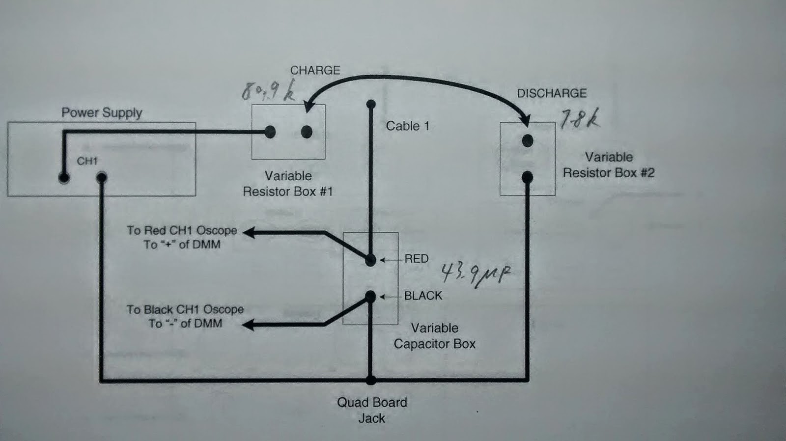
First, we found the values of the components when the circuit is charged and discharged in the circuits below.


We used this oscilloscope to perform the lab but unfortunately it only gave instantaneous voltage. So we illustrated the response of the capacitor charging and discharging.


 We used a stopwatch and a voltmeter to measure the voltage of the charging capacitor within 20 seconds.

Materials 1 Voltmeter and 1 stopwatch (optional), 1 oscilloscope, 2 variable resistors, 1 33 microfarad capacitor, cables.


For a charging time of about 20 seconds the voltage was 11 volts. The discharge time was about 2 sectonds.

Leakage Resistance:


Error calculation:


This was how the discharging graph should have appeared over time.


Conclusion:
The lab demonstrated the rapid discharge rate of a capacitor and the reasonable energy storage that can be achieved with the correct circuitry. The experiment was valid and the leakage resistance was about 10 times the charging resistance. This was the same ratio of the charging to discharging times of the capacitor.