Wednesday, May 21, 2014

AC Circuit Analysis


Complex Numbers Freemat


In this activity we learned how to use Freemat to easily calculate complex solutions.

Integrating and Differentiating Op Amps

We observed the effects of integrating and differentiating op amps


This integrating op amp shows the yellow sinusoidal output with smaller amplitude to the integration effect of the op amp.


At this point the op amp was becoming saturated.

This differentiating op amp created a phase shift and decrease in amplitude in yellow.

In each case the frequency was maintained despite the operations, which is expected of  AC circuits.

Monday, April 28, 2014

Capacitor Charging/Discharging

Introduction:
Capacitors are electrical components that store energy in the electric field and can rapidly charge or discharge the energy if needed. In this lab we observed the charging and discharging of a capacitor in the circuit as is dumps it energy.

Procedure:
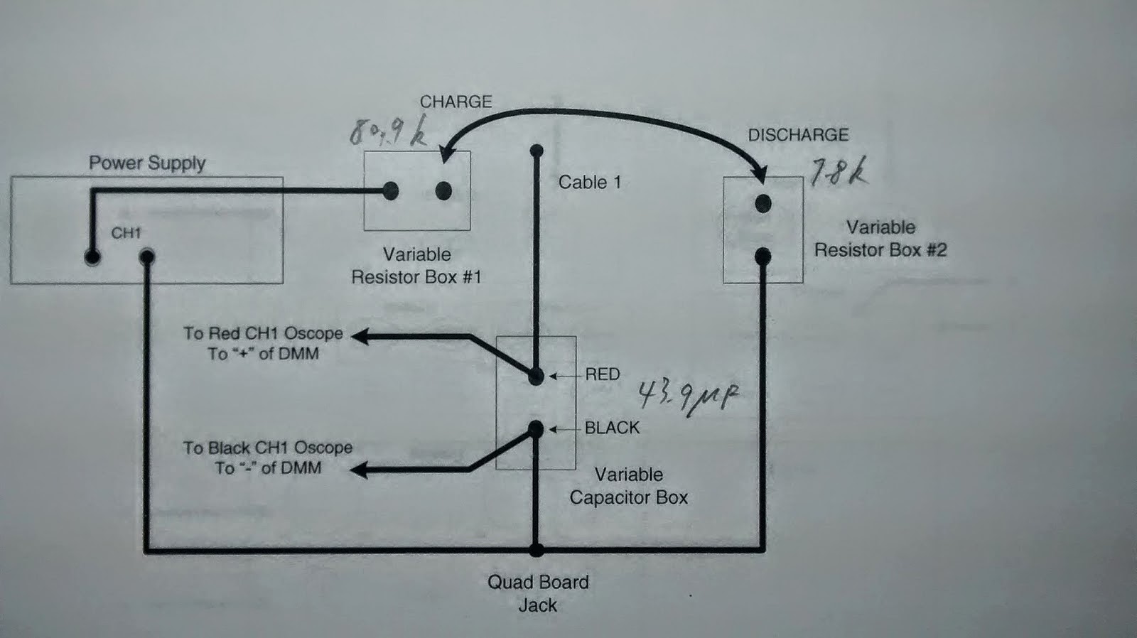
First, we found the values of the components when the circuit is charged and discharged in the circuits below.


We used this oscilloscope to perform the lab but unfortunately it only gave instantaneous voltage. So we illustrated the response of the capacitor charging and discharging.


 We used a stopwatch and a voltmeter to measure the voltage of the charging capacitor within 20 seconds.

Materials 1 Voltmeter and 1 stopwatch (optional), 1 oscilloscope, 2 variable resistors, 1 33 microfarad capacitor, cables.


For a charging time of about 20 seconds the voltage was 11 volts. The discharge time was about 2 sectonds.

Leakage Resistance:


Error calculation:


This was how the discharging graph should have appeared over time.


Conclusion:
The lab demonstrated the rapid discharge rate of a capacitor and the reasonable energy storage that can be achieved with the correct circuitry. The experiment was valid and the leakage resistance was about 10 times the charging resistance. This was the same ratio of the charging to discharging times of the capacitor.


Monday, April 14, 2014

Practical Signal Conditioning

Introduction:

The purpose of this lab was to use an operational amplifier to perform an operation and observe a signal. We used a LM35 semiconductor to translate the ambient air temperature into a voltage signal. This would give us a temperature which would be converted into the Fahrenheit scale from the Celsius scale through the op amp. 

Procedure:
   We tested the LM35 with 9 V into it relative to ground and seeing what voltage we get as output. We go an output current of 220 mA which was a magnitude representation of the ambient room temperature.

Add caption
 We found the necessary and available resistors to get the proper conversion factors to convert the signal voltage into the comparable Fahrenheit voltage. 


We then connected the LM35 to the op amp into the circuit shown. We also used a potentiometer to adjust the input voltage and the output we got:


Using the temperature equation we found the output current to be 0716 A.
The error is shown here.


Conclusion:
This application of op amps demonstrates a practical use of signal conditioning for observing the temperature. It is much more convenient to have a real time temperature with simple signals than to have to convert the temperatures otherwise. The error may have be due to approximations in calculations.

Tuesday, April 1, 2014

Operational Amplifiers 1

Introduction:
The purpose of this lab is to condition a signal from a voltage input to a required voltage output.
- Set up voltage divider circuit in order to obtain signal voltage in DC
- Set up Inverting op amp circuit that conditions signal from 0 to 1 v to 0 to -10v
- measure the values
- conclusion

Procedure:
We first had to find the necessary resistors for this circuit by finding an appropriate ratio and looking at the available resistors.
-The sensor may only output a maximum of 1 mA of current.

Vcc = 12 V.
Vee = -12 V. 
Vin = 0 V to +1 V.
Vout = 0 V to -10 V.


Then we created a voltage dividing circuit that would give us the correct 1 V drop across the input and output, which can be modified with the POT.


Ry = 909 Ohm


To make sure the resistor Rx does not surpass the power limit we calculated the minimum possible resistance.


Rx_min=1152 Ohms, but we will use 1300 ohms as We used a 1300 Ohm resistor to be safe.


For Rx at 1300 Ohms we recalculated 
Ry = 118 Ohms


To avoid unappreciable loading of the divider circuit with too low resistances we used a 10k Ohm Rx value instead.


These values are what we used for our model.


By decreasing the value of the POT to a value lower than 909, we were able to obtain necessary voltages for the signal input.

This is what our circuit and testing looked like.


Testing for all the voltages and caluclating the necessary values gave us the following table.


Conclusion:
     The results conclude that there was a gain of -10 through the OP amp, which conditioned the signal to the desired voltage. The current did not exceed 1 milliamp and the voltage divider resistor remained in tact. We were able to successfully condition a signal for the various voltages and see the expected gains.